

Let’s Get It Clear: Measurements in seating – Absolute angles in seating system measures
In the previous articles we looked at how parts of the body and a seating system are measured in relation to each other and at how parts of the body are measured in relation to the outside world. In this article we cover the standardised ways of measuring the angles of components of a person’s seating system as these measures relate to the outside world.
Absolute angle measures of the components of a wheelchair and its seating system help to ensure the seating system meets the needs of the occupant, and have their value for an engineer who is setting up the individual components of a seating system prior to its delivery. Absolute angle measures relate to the outside world, where our references in normal life are gravitational, i.e. to the vertical and, at right angles to the vertical, to the horizontal. Each component of a seating system has the potential to have its angles set up for the client’s positioning needs, and frequently can be adjusted 3-dimensionally in each of the sagittal (side view), frontal, and transverse (viewed from above) planes.
For measuring the angles of any wheelchair seating component in any of these planes, each component will refer back to the wheelchair assuming that it’s standing on a horizontal surface. One horizontal axis is established by the line through the centres of the main wheel axles. The other horizontal axis is at right angles to the first one. The third axis is the vertical. Measuring angles follows the same Right Hand Rules that we use for measuring absolute angles of the body.
Right Hand Rules
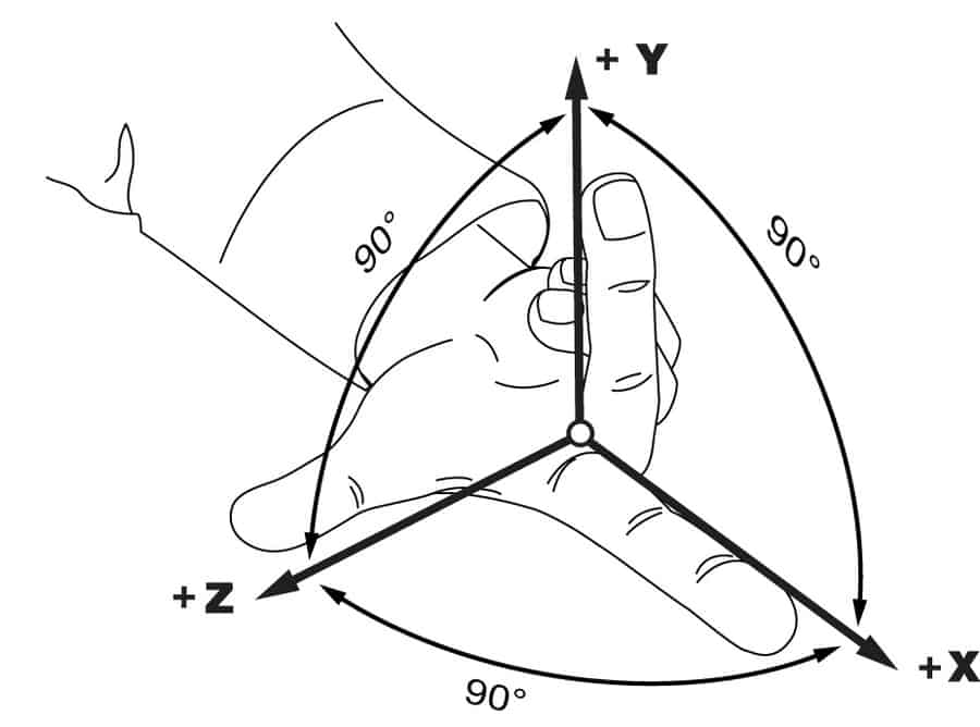
There are two ‘Right Hand Rules’ involved, and are detailed in a downloadable Clinical Application Guide (CAG)1 to the standard written to cover body and seating measures2. The first Right Hand Rule relates to the axes described above, and is depicted by using the thumb and the first two fingers of the right hand, with each digit at right angles to each other (see Figure 1). In a wheelchair, the half way point between the two main wheel axles is the zero starting point for this rule. From this point there’s the vertical (y) axis (the middle finger), and the two horizontal axes. The first of the latter (the z axis) goes off to the right (the thumb), and the other (the x axis), at right angles, to the front (the forefinger).
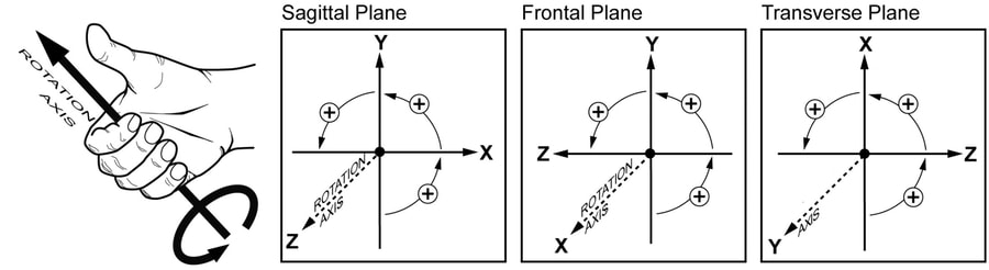
The rules for measuring the direction and amount of rotation come from a second Right Hand Rule. There is a clockwise direction of rotation which is designated as a negative angle, and an anti-clockwise which is a positive angle. To know which is which, place the thumb of your right hand pointing outwards along the axis in question, and curl your fingers. The fingers point in the positive (anti-clockwise direction) (Figure 2).
What are the lines we are measuring?
To start with, it’s relatively easy to describe the absolute angles of the solid (metal or plastic, usually) components of a wheelchair. Flat even-thicknessed components of a seating system placed parallel with each or any of the reference planes are straight forward. The top surfaces of an inferior support, such as a seat cushion, will be parallel with the bottom surfaces of the component, and so one could use either surface for measuring any deviation from the horizontal, though the measurement standard references the surface which is closest to the body – see the examples below.
It’s the upholstered or padded parts of the attached seating system components that can be more challenging, especially where there is shaping involved. For the clinician, it will be the surface of a postural support device (PSD) (such as a seat cushion, back support, lateral thigh pad, etc.) where it interfaces with the body that is of most interest. (Whereas, for the wheelchair technician, it will be the surface of the PSD where it interfaces with the wheelchair structure that is more relevant.) For a contoured surface, the centreline of the part of the surface in contact with the body of the seated occupant is used for the measures.
Seat cushions
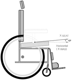
In practice, a wheelchair seat cushion’s upper surface is seldom horizontal as viewed from the side. The front is usually higher than the back: this will be a positive angle (Figure 3). If the cushion is thicker at the front than at the back, then the angle of the top surface would be greater than the lower surface.
In some instances, from the frontal view, while the base is likely to be horizontal to attach to the horizontal seat rails of the wheelchair, the top surface may be higher on one side than the other to accommodate or compensate for a pelvic obliquity. If the latter is higher on the left, this will be a positive angle, whereas if higher on the right this will be a negative angle (Figure 4).
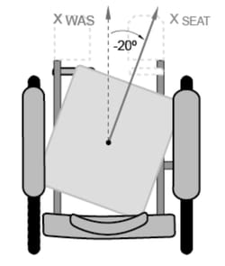
Commonly, the seat cushion is parallel with the chair seat rails when viewed from above, but if the cushion’s centreline is rotated to accommodate, for example, windswept thighs, then this degree of rotation can also be measured using the Right Hand rule with clockwise rotation being a negative angle (Figure 5).
Positioning supports
Secondary positioning supports, such as lateral trunk supports, lateral thigh supports, inferior foot supports, etc., often need to follow the wheelchair occupant’s body surfaces more closely in all three dimensions than the primary supports of the seat cushion and back support (which are more likely to follow the fixed components of the wheelchair frame).
To be effective, these secondary supports need to be readily adjustable in all three planes, and it’s essential for the clinical outcomes requiring their prescription that they are adjusted accurately.
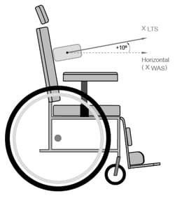
Here, as an example, we will look at lateral trunk supports, but these measures are no different in application than for any other lateral supports. First, we will look at the sagittal (side) view (Figure 6). This angle can be measured where there is at least one straight edge of the support.
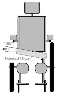
If the pad were circular, then there would not be a relevant sagittal angle for the pad, but there could be for its mount. In the illustration, the support is mounted to the back support, and therefore this lateral support absolute angle would change if the seat back were reclined: the clinical implications to the changed position of the support to the trunk should be considered.
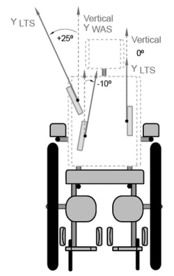
From the frontal view, in this illustration there’s three supports, each of which is at a different angle from the vertical (Figure 7). This scenario could arise when managing the positioning needs of a person with a scoliotic spine. This example shows that the supports can commonly range from being at a positive to a negative angle.
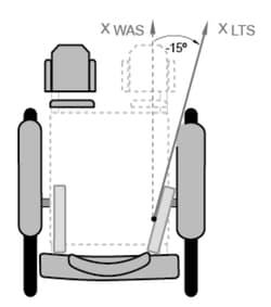
Finally, we have the transverse view from above which reflects the prescribed angle in the third dimension (Figure 8).
Summary
The two Right Hand Rules give us a standardised means to measure the angular position of different elements of a wheelchair seating system as measured against the gravitational axes of a wheelchair and against the outside world.
As with previous articles in this series, the reader should consult the Clinical Application Guide (CAG)1 from which the images in this article have been sourced.
The CAG gives worked examples for many more inferior, posterior, anterior, medial, and lateral supports, together with detailed guidance as how to make the measures, the clinical importance of each measure, and how they link to, and compare with, related body absolute angles.
References
- Waugh, K and Crane, B (2013) A clinical application guide to standardized wheelchair seating measures of the body and seating support surfaces. Accessible as BPG3 from www.pmguk.co.uk/resources/best-practice-guidelines/bpg-archive
- ISO 16840-1:2006 Wheelchair Seating, Part 1 – Vocabulary, reference axis convention and measures for body posture and postural support surfaces
Further items can be found at www.beshealthcare.net. If you are interested in receiving further information on the topic, please contact  barend@beshealthcare.net.
Dr Barend ter Haar has been involved in seating and mobility for over 30 years, including lecturing internationally and developing international seating standards.